| |
|
Application of construction
in preflex composite girder with loading |
 A SPECIAL FEATURE A SPECIAL FEATURE
1. A summary of the method
(Patent
a public notice Number. 10-2000-0036947),
(Registration number.
20-0196863-0000, Registration number20-0210596-0000)
The building construction
using the basic preflex beam is difficult to obtain
vacant room effectively because
of the bigger negative moment rising in connection
with column of section part than positive moment rising
in central parts when design
load is acted, and brought rusting of steel and a declination
of durability because of rising
cracks of concrete , and gave damages of connection
parts of a pole and a crossbeam, and gave magnification
of column section because of
increasing of dynamic load being due to excessive dead
load.
the applicable method
of the successive preflex composite beam using loading
produces positive moment with stocking a little load
to the central parts of Beam
after leaving preflex beam producing as simple beam
state simply between pole and
pole, and decline tensile force confronting design load
with using a compressed power of beam section part originated
from excluding the stocked load
after continuity with connecting preflex beam and beam
by welding
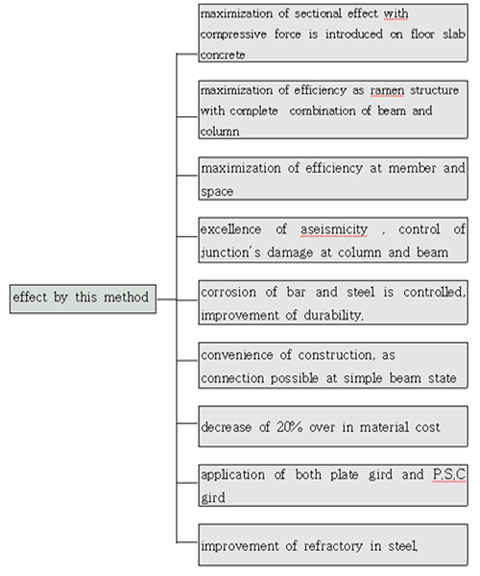
2. effect
·
the continuous structure using the basic preflex composite
girder was unavoidable interpretation,
but preflex composite girder using this method
can maximize a section effects being
due to possibility of interpretation as composite
beam
· efficiency as rahmen
can be maximize because perfect firmness is possible
between beam and pole
· that can maximize the efficiency
of member and space
· that can repress damages of
connection between pole and beam effectively and
aseismicity is excellent.
· rusting of bar and steel can
be improved being due to controling fissures rising
from floor slab concrete
· Construction is easy and reliable
because this method connect between beam and
beam inside pole of simple beam situation.
· when you apply this method ,
you can decline about 20% of the material cost.
· this method can be applied
to plate girder, p.s.c girder, and so on as well.
|
¡¡
Application of construction
in preflex composite girder with loading |
THE METHOD OF MAKING
1. we make a large quantity of preflex beam
in factory and transport to the actual spot
of cause, we can make in the actual spot.
2. in case of concrete pole , we should do
placing and curing pole ,
and should draw out steel which is needed in case of
steel composite pole, we should
do placing and curing concrete in low parts
which is stayed by beam , and
we should obstruct bucking of pole, and we should make
a situation of putting
simply preflex composite beam, welding braket to the
web part of steel.
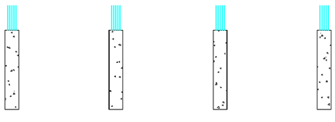
Fig 1 Concrete Column

Fig 2 Steel Composite Column
3. you should leave simply preflex to the pole
in this time , in concrete cases , you
should do boring to the lower part casing concrete of
section part and to the upper-lower
part flange, and then you should help steel of pole
can be penetrated.
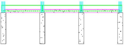
Fig 3 Concrete Column
¡¡ |
¡¡
Application of construction
in preflex composite girder with loading |
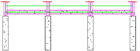
Fig 4 Steel Composite Column
4. you connect lateral stiffening , at this
time , in case of concrete pole , you do boring
to the upper-lower part flange laying in the pole ,
and then you do penetrate steel.
you connect span central lateral stiffening with preflex
beam as main beam in similar
methods like picture 5.
picture 5. - connection details picture
of preflex beam and lateral stiffening
main
beam cross beam The lower casing concrete
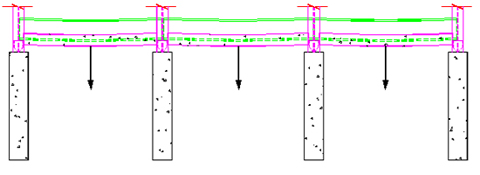
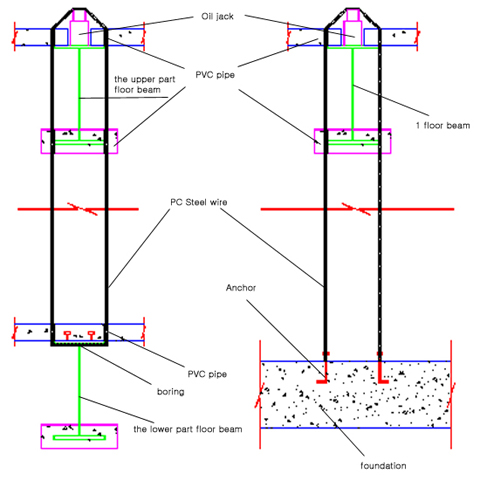
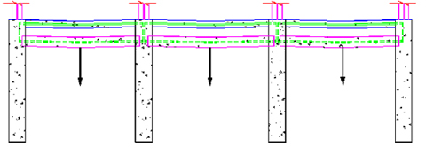
5. you do stock vertical load to the preflex
beam leaving , you can do stock load
with establishing anchor in basic bottom in first floor,
you can do stock load with laying
in floor slab concrete and coiling in the main beam
of lower part floor pc strong
line in second floor , the picture 8 shows the picture
of bending moment being owing
to self load and load stock, and picture 9 express the
methods stocking load with being
tense pc strong line as tension equipment ,and
express the methods stocking load with laying in anchor
in the basic bottom as basic
picture.
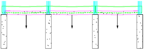
picture 6- situation picture of stocking
load to the preflex beam in cases of
¡¡ |
¡¡
Application of construction
in preflex composite girder with loading |
picture 7. situation picture stocking
load to the preflex in cases of steel composite column.

picture 8. Moment picture of preflex
as beam self load and load stock
¡¡ |
¡¡
Application of construction
in preflex composite girder with loading |
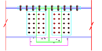
6. in cases of concrete pole ,
we do weld and connect using cover plate between
preflex beam as main beam of simple setting state
and beam in cases of steel composite
pole, we make successive structure with welding and connecting preflex beam using joint bar in the web part of pole. the picture 10~12 show details of
connection between main beam and lateral stiffening
to the part of pole in case of concrete pole. he
picture 13 shows details connection
between main beam and lateral stiffening in
case of steel composite column
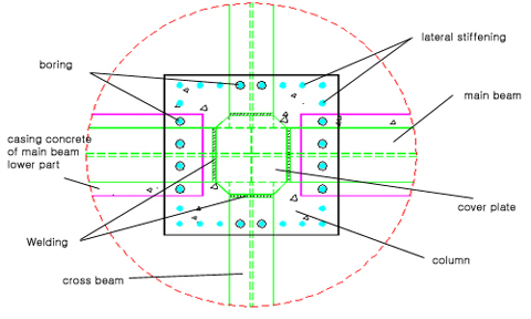
Fig 10
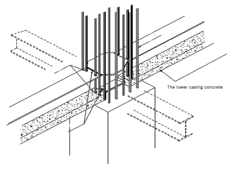
Fig 11
¡¡ |
¡¡
Application of construction
in preflex composite girder with loading |
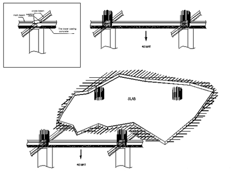
Fig 12
¡¡
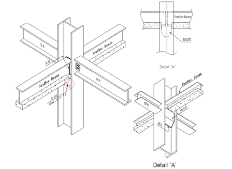
Fig 13
¡¡ |
¡¡
Application of construction
in preflex composite girder with loading |
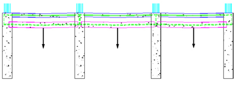
7. Upper column, floor
slab have simultaneous placing and curing. As
column and beam become one body , they can composed
behavior in given load. Picture
16 is bending moment diagram that is happened in preflex composite beam of continuous
structure state about load of it hasn't set concrete.
Picture 14 concrete column
¡¡
Picture 15 Steel composite column
¡¡

Picture 16 that is happened
in preflex composite beam of continuous structure state
about load of it hasn't set concrete.
¡¡
8. Surcharged load is remove. This time, as
bending moment of picture 18 is happened.
as a result of this, section of beam is introduced
and negative moment by service
load is resisted as floor slab and composited beam.
¡¡
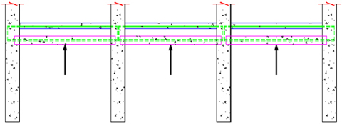
Picture 17 upward force by removed
weight
¡¡ |
¡¡
Application of construction
in preflex composite girder with loading |

Picture 18 bending moment diagram
of preflex composite beam is happened by load
removed.
From picture 1 to picture 18, the negative
moment section of the construction process introduced
compressed stress and have resisted negative moment
by dead load, service load.
Because
this method have decreased exaggerative moment at union
part of beam and column, can prevent a lack of
water by union part floor concrete's crack at
previous construction.
So this has not only
improvement of endurance but also decrease of
column section as well as decrease of beam steel
height. As this result can cut down on material
cost, maximize efficiency of space, make possible production
of construction that have improved aseismicity
by self load reduction of beam and continuance.
This method can applied not only preflex beam
but also P.S.C continuance beam, Plate gird, steel
box. naturally this method can applied on repetition
of a same way at continuance of 3 span over.
¡ß If show by a diagram construction
step and way of this method.
|
¡¡
Application of construction
in preflex composite girder with loading |
example of a
design
1.examination
section in case of possession load 0.5 ton/m2 (Using
of SWS 490) - when
load 20 ton.

picture19
¡ß Section of inner
part span length 30m part by this loading used method
1. To simplicity of
structural calculation, selection predicted the upper
center part
that will get the most load. Span of main beam
is 25.0m+30.0m+25.0m=80.0m, Modelling Space of main beam is 3@10.0m =30.0m.
2. Structural system is modeled
classified by each construction stage that presented
above.
3.Computation of
load
-
acting possession load on floor slab : 0.5 ton/m2
-
Self load of lateral stiffening member. :0.12 ton/m
- Self load
of slab : is applied load of 0.375 ton/m2 over
4. Stress examination
Examination
of stress is examined that the most moment is applied
30m span's
main beam as steel upper flange's stress of negative
moment part in preflex
composite beam and lower casing concrete's stress of
span center part.
-The section property
¡¡ |
negative
moment part |
positive moment part
steel + lower casing concrete
¡¡ |
steel
+lower casing concrete +floor slab |
I |
1516520.8
¡¡ |
2052417.5 |
2723094.6 |
Yu |
48.5
¡¡ |
62.2 |
69.2 |
YL |
48.5
¡¡ |
47.8 |
55.8 |
¡¡ |
¡¡
Application of construction
in preflex composite girder with loading |
|
stage |
moment(t.m)
|
stress(Kg/§²) |
part of end |
center |
steel
upper flange of end part |
lower
casing concrete of center
¡¡ |
preflex beam
(early creep, early
shrinkage, consideration of self load)
¡¡ |
|
|
0 |
-165.85 |
loading
¡¡ |
0 |
150 |
0 |
46.6 |
Self loading of floor
concrete and lateral stiffening member.
¡¡ |
-340.6 |
180.6 |
1089.5 |
56.1 |
Removal
of load
¡¡ |
77.8 |
-81.4 |
-155.0 |
-22.2 |
loading
of occupation load
¡¡ |
-371.5 |
217.3 |
739.5 |
59.4 |
Sum
¡¡ |
¡¡ |
¡¡ |
1465.5 |
-26.0 |
-The next is expressed
stress of section that in case of unloading and considering
by classified loaded magnitude in 30m section.
a
reference |
steel
upper flange's stress of negative moment
part |
lower casing concrete's stress of
span cente
¡¡ |
unloading
¡¡ |
2097 |
-50.4 |
loading
5ton of this method
¡¡ |
1603 |
-44.3 |
loading
10ton of this method
¡¡ |
1557 |
-38.0 |
loading
15ton of this method
¡¡ |
1511 |
-32.0 |
loading
20ton of this method
¡¡ |
1465 |
-26.0 |
¡Ø here, in case of unloading, the reason
that stress of steel upper flange in negative
moment part grow bigger suddenly, compressed stress
hasn't introduced
on floor slab concrete of section part by loading removal
so because it isn't
considered as composite section.
|
¡¡
Application of construction
in preflex composite girder with loading |
2.
examination section in case of possession load 1.2 ton/m2
(Using of SWS 490)
picture20 Section of inner part span length
30m part by this loading used method
- At same condition such (1), Only possession
load applied as 1.2 ton/m2.
- The
next is expressed stress of section that in case of
unloading and considering
by classified loaded magnitude in 30m section.
a
reference |
steel
upper flange's stress of negative moment
part |
lower casing concrete's stress of
span cente
¡¡ |
unloading
¡¡ |
2051 |
-66.7 |
loading
5ton of this method
¡¡ |
1528 |
-63.8 |
loading
10ton of this method
¡¡ |
1500 |
-60.8 |
loading
15ton of this method
¡¡ |
1473 |
-57.8 |
loading
20ton of this method
¡¡ |
1446 |
-54.8 |
¡Ø
here is on equal terms, in case of unloading, the reason
that stress of steel upper
flange in negative moment part grow bigger suddenly,
compressed stress
hasn't introduced on floor slab concrete of section
part by loading removal
so because it isn't considered as composite section.
|
¡¡
Application of construction
in preflex composite girder with loading |
effect by this method
As mentioned,
compared with section of previous preflex continuance
beam that can maintain stress of negative
moment part in similar level, section of
this method can reduce about 5% of steel and 45% of
the lower casing concrete.
¡¡ |
|
|
|
|