|
 The new method of preflex beam
¡¡
The abstract of Preflex Beam
¡¡
The Preflex composite girder is
well-known and constructed worldwide. It was initially proposed
by the Belgium designer of structure , A. Lipski in 1949. From 1951
to 1954 A. Lipski and professor L. Bases, Brussel Univ. jointly
researched and developed the Preflex composite girder bridge. It
makes up for the weak point of concrete which is brittle and weak
in tensile. Now the superiority of Preflex composite girder bridge
is guaranteed worldwide. The pre-compressed casing concrete covering
tensile flange can counterbalance tensile stresses due to dead and
live load. This method is an economical method of construction and
its characteristic is as follow.
The safety and durability
¡¡
The Preflex composite girder is
safer than other steel girder or concrete girder under service load
because maximum bending tensile and compressive stresses occur when
it is manufactured.
It has bigger rigidity, corrosion
resistance and durability because its lower flange is covered with
high strength concrete and the whole steel girder is covered with
concrete.
¡¡
The workability and availability
This method can reduce a term of
work for using Preflex girder manufactured in factory and can reduce
construction price because we can construct slab without additional
support system.
If you apply the method under following
conditions, you can take advantage of its merits because of relatively
lower height of girder.
¨ç In case of limited height of
girder for changing work to repair river.
¨è For reducing maintenance expenses
or getting easiness of construction.
¨é When we construct grade separation,
subway and pedestrian over bridge that must make space under bridge,
Preflex composite girder is applied in form of simple beam or continuous
beam and nowadays Preflex composite girder of block form constructed
is using.
¡¡
The comparison with a bridge
that is using other method of construction.
It is the one of the best advantages
that we can reduce height of girder. It is widely known that it
can has 45 of span-height ratio and 50 of the least height of girder.
We can say that Preflex coposite
girder is safer from fatigue than common plate girder because the
range of stress the former is smaller than that of latter.
Because it has bigger rigidity than
common plate girder, deflection and vibration is very small. And
the maintenance expense is cheaper because it is covered with concrete
completely.
¡¡
2nd prestressing for simple and continuous preflex composite beams
¡¡
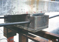
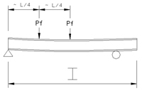
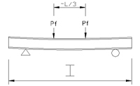
2nd prestressing for simple preflex composite beams using PC steel
bar
An outline of the above method is
as follow.
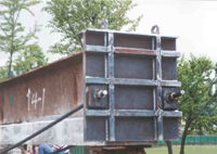
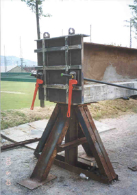
In advance set Preflex composite
girder beam manufactured in factory or field between abutment or
bridge pier. And after connecting end of beam with PC steel bar
by using anchor plate, equip hydraulic jack 1/3§¤point from end
of bridge on either side. By use of this hydraulic jack tense the
PC steel bar then cast and cure concrete when bending occurred at
beam. Next remove the PC steel bar so give additional compressive
stresses to lower part of beam at range of the positive moments.
Contents of construction |
Procedure of construction |
Setting Preflex composite
girder beam |
 |
Connecting steel bar, Installing
hydraulic jack and Loading by steel bar |
 |
Casting Slab In Condition
of Loading |
 |
The secondary tensing steel
bar right after casting slab - Supplement of compressive
stresses loss which is occurred right before curing |
 |
Paving asphalt after removing
steel bar and hydraulic jack - Diagram of normal stress
and moments |
 |
Classification |
Detail drawing and foreground
of experiments |
Detail dra-wing of conn-ecting
steel bar with anc-hor plate |
End |
 |
Mid span |
 |
Connecting
steel bar with anchor plate |
 |
 |
. |
 |
¡¡
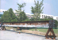
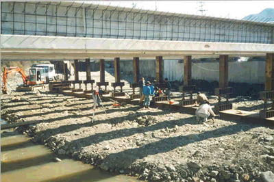
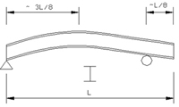
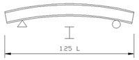
2nd prestressing for simple preflex composite beams by lifting
temporary support
Contents of construction |
Procedure of construction |
Setting Preflex steel girder |
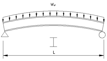 |
Preflexion loading at
about L/5 point from both of ends |
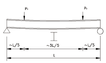 |
Casting concrete at lower
flange and releasing stresses |
 |
Lifting up sub-support at
mid span |
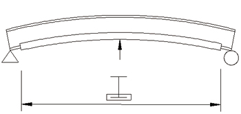 |
Casting concrete of slab and
web |
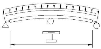 |
Lifting down sub-support |
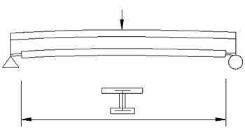 |
Paving asphalt |
 |
|
Execution of work |
Foreground of installing sub-support |
|
¡¡
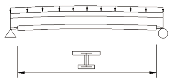
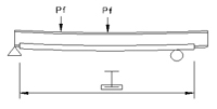
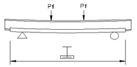
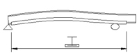
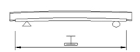
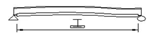
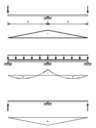
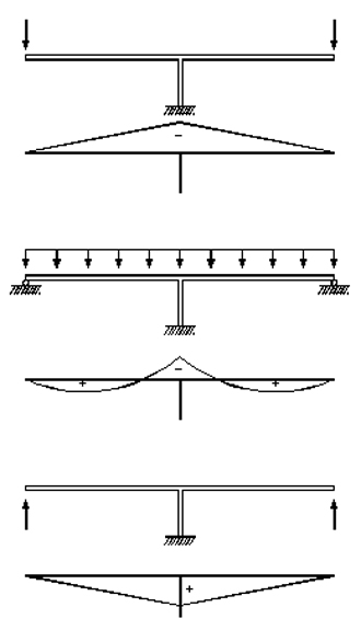
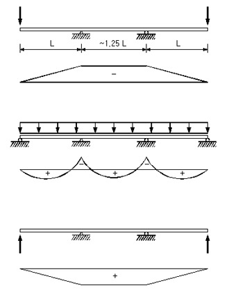
2nd prestressing for simple preflex composite beams by shifting
down-up support
¡¡
First convert hinge support to fixed
ends on simple beam structure system and lift down roller support
to give additional compressive stresses to lower flange. In this
condition cast slab concrete. After the slab concrete is cured,
lift up the roller support for giving compressive stresses corresponding
to negative moments of fixed ends to slab concrete.
¡¡ |
Procedure of construction |
States and moments according
to stages diagram in case of using Down-up method |
 |
|
Detail drawing |
Connecting Preflex beam with
bridge pier at fixed support |
 |
¡¡
The manufacturing method of inner and outer preflex girder for
manufacturing continuous preflex composite beams
In the first place, manufacture
Preflex girder in lots according to inner and outer span to make
Preflex beam of continuous beam. The next give secondary prestressing
by Down-up method after connecting inner and outer Preflex girder
according to each span. The progress of construction Preflex composite
girder is as follow.
Contents of construction |
Procedure of construction |
Outside beam |
Inside beam |
Setting Preflex steel girder |
 |
 |
Loading Preflex loads |
 |
 |
Casting lower flange concrete |
 |
 |
Release |
 |
 |
¡¡
2nd prestressing for 2 spans continuous preflex composite beams by
shifting down-up support(type separated beam from pier)
First connect two external beams
on the inner support. And cast slab concrete in condition that both
ends of external beams are lifted down. After the slab concrete
is cured, lift up the both ends of external beams for giving compressive
stresses to slab concrete corresponding to tensile stresses of inner
supports.
|
Procedure of construction |
Setting into simple beam by
shifting inner support of outer span beam |
 |
States and moment diagram
according to each stages in case of using Down-up method
after connecting two outer beams with inner support |
 |
¡¡
2nd prestressing for 2 spans continuous preflex composite beams by
shifting down-up support(type interated beam from pier)
The moment that two outer beams
are connected make them be in a body with bridge pier. Then cast
slab concrete in condition that both ends of external beams are
lifted down. After the slab concrete is cured, lift up the both
ends of external beams for giving compressive stresses to slab concrete
corresponding to tensile stresses of inner supports.
¡¡ |
Procedure of construction |
Setting into simple beam by
shifting inner support of outer span beam |
|
States and moment diagram
according to each stages in case of using Down-up method
after connecting two outer beams with inner support) |
 |
|
Detail drawing |
Connecting Preflex beam with
bridge pier in one unified body at inner support |
 |
¡¡
2nd prestressing for 3 spans continuous preflex composite beams by
shifting down-up support(type separated beam from pier)
First connect two outer beams with
inner support respectively. Then cast slab concrete in condition
that both ends of external beams are lifted down. After the slab
concrete is cured, lift up the both ends of external beams for giving
compressive stresses to slab concrete corresponding to tensile stresses
of inner supports.
|
Procedure of construction |
States and moment diagram
according to each stages in case of using Down-up method
after connecting two outer beams and inner beams with
inner support respectively |
 |
¡¡
2nd prestressing for 3 spans continuous preflex composite beams by
shifting down-up support(type integrated beam from pier)
¡¡
The moment that two outer beams
are connected make them be in a body with bridge pier. Then cast
slab concrete in condition that both ends of external beams are
lifted down. After the slab concrete is cured, lift up the both
ends of external beams for giving compressive stresses to slab concrete
corresponding to tensile stresses of inner supports.
|
Procedure of construction |
States and moment diagram
according to each stages in case of using Down-up method
after connecting two outer beams and inner beams with
inner support and making them be in a body simultaneously(Here,
the condition connected beam with bridge pier is same
with the case of 2 spans continuous beam) |
 |
|