| |
|
The method of improving stiffness
at the inner support in the steel box girder. |
 Because
the construction work of existing steel box composite
girder bridge is faster than the other method,
it has been widely constructed in the inside and outside
of the country. Because
the construction work of existing steel box composite
girder bridge is faster than the other method,
it has been widely constructed in the inside and outside
of the country.
Because of grate the torsion, that
has many advantage for the curve bridge but has
comparative big section, noise and vibration.
Steel box composite
gird bridge by concrete-fill and lifting support method.
Because
the construction work of existing steel box composite
girder bridge is quick than the other method,
it has widely constructed in the inside and outside
of the country. Because of grate the torsion, that has
many advantage for the curve bridge but has comparative
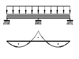
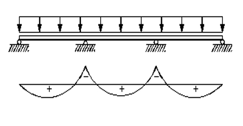
big section, noise and vibration. There are so different
between maximum magnitude of positive moment and
negative moment. The section choice of bridge whole
length is non economic and because the floor
slab's section is large, neutrality axis give way to
the upper part. So the upper and lower stress of
steel not be in balance. The other a fault of previous
steel box girder bridge is extension that happened at
inner support part by additional dead and live load. Therefore
it becomes not composite section, floor slab is
cracked and stiffness is declined. Fault
at welding area is due to the shear flow's disturbance
by changing top and bottom flange thick into various
shape.
Steel box composite gird bridge by concrete-fill and
lifting support method.
(The new method No.270
appointed by MOCT [Ministry of Construction& Transportation])
(Patent a public notice Number. 10-1999-007688)
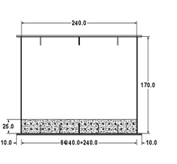
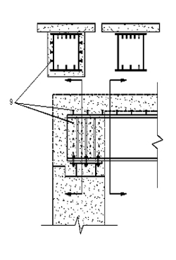
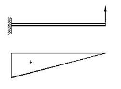
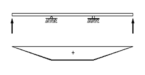
This method's purpose is improving
stiffness necessary to negative moment area by
shear connector installed and casting concrete on the
bottom of the negative moment area of the steel box
to steel box girder.Otherwise, improving stiffness
necessary for taking off tension force when design load
applied by using the up-down method, compressive stress
installed on the negative moment area of upside of deck
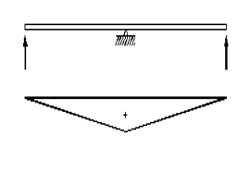
plate concrete. This method is more extend a span
of bridge than existed steel box bridge and case
of making a variety section of the positive-negative
moment area, most extend a span of bridge.Otherwise
prevent a decay in the steel box by being installed
concrete at the bottom of the negative moment area and
obtain effect that absorbed noise or shake.And
This method can reduce a fault of welding area by changing
top and bottom flange thick into relatively simple. |
¡¡
The
method of improving stiffness at the inner support in the
steel box girder. |
45m 2 span
continuous bridge 's section property and comparison in
the amount of materials
Reduced effect of steel materials.
flange's thickness and hight's simultaneous
reduction and maximum curtailment of steel
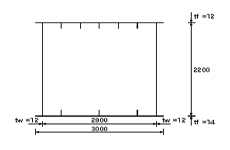
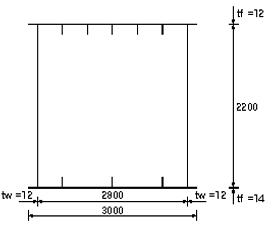
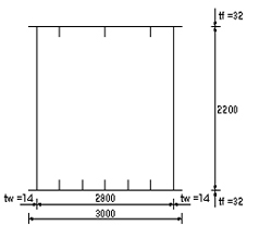
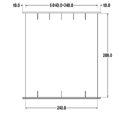
existing steel box gird bridge's section property
steel : SM490
concrete : The floor plate -
270 Kg/§²
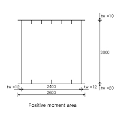
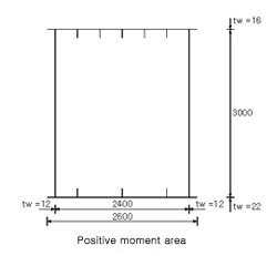
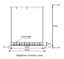
The main position's section
positive moment area |
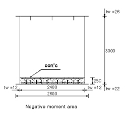
negative moment area |
 |
 |
TU=1.2cm , TL=1.4 cm |
TU=3.2 cm , TL=3.2 cm |
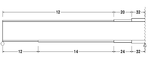
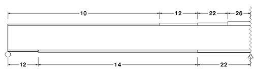
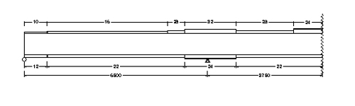
The variation of flange
|
The
method of improving stiffness at the inner support
in the steel box girder. |
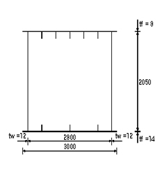
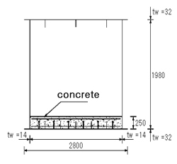
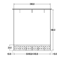
improved steel box
gird bridge's section property
steel : SM490
concrete : The floor plate -
270 Kg/§² casting concrete :-400 Kg/§²
The
main position's section
positive moment area |
negative moment area |
 |
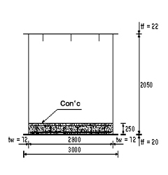 |
TU=0.8
cm , TL=1.4 cm |
TU=2.2
cm , TL=2.0 cm |
variation of flange
The section and the amount of materials's
comparison
|
existing |
improved |
existing/improved |
steel |
120.5 |
102.67 |
0.85 |
concrete |
315 |
332 |
1.05 |
section's
girder height |
positive moment area |
2200 |
2050 |
0.93 |
negative moment area |
2200 |
2050 |
0.93 |
girder height 7% reduction
a condition ¡æ15% reduction of steel amount
|
¡¡
The
method of improving stiffness at the inner support
in the steel box girder. |
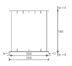
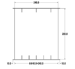
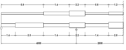
The effect of reduction
on girder height
flange's thickness and hight's
simultaneous reduction and maximum curtailment of
girder height
The
main position's section
positive
moment area |
 |
 |
negative
moment area |
 |
 |
The
section and the amount of materials's comparison
|
existing method
¡¡
|
Lifting
Support |
L.S/Existing
|
Steel (ton ) |
120.5 |
116.35 |
0.97 |
section's girder heigh |
positive
moment area |
2200 |
1980 |
0.90 |
negative
moment area |
2200 |
1980 |
0.90 |
3.5% reduction
of steel amount¡ægirder height 10% reduction(220cm¡æ198cm)
|
¡¡
The
method of improving stiffness at the inner support
in the steel box girder. |
40m-50m-40m45m 3
span continuous bridge's section property and comparison
in the amount of materials
Reduced effect of
steel materials.
Flange's thickness and hight's simultaneous reduction
and maximum curtailment
of steel amount
existing steel box gird bridge's section property
steel : SM 490
concrete : floor plate 270 Kg/§²
The main position's
section
positive moment area |
negative moment area |
|
 |
TU=1.2
cm , TL=1.4 cm |
TU=2.6
cm , TL=2.6 cm |
The variation of flange
|
¡¡
The
method of improving stiffness at the inner support
in the steel box girder. |
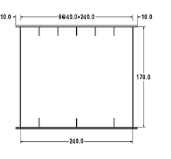
improved steel box
gird bridge's section property
steel : SM490
concrete
: The floor plate - 270 Kg/§² casting concrete :-400
Kg/§²
The main position's
section
positive moment area |
negative moment area |
 |
 |
TU=0.8
cm , TL=2.0 cm |
TU=2.2
cm , TL=2.2 cm |
The variation of flange
The section and
the amount of materials's comparison
|
existing method |
Lifting
Support |
L.S/Existing
|
Steel (ton ) |
155.14 |
116.35 |
0.97 |
concrete (ton ) |
493 |
520 |
1.05 |
section's girder heigh |
positive
moment area |
2000 |
1880 |
0.94 |
negative
moment area |
2000 |
1880 |
0.94 |
girder height
6% reduction a condition ¡æ14.9% reduction of
steel amount
|
¡¡
The
method of improving stiffness at the inner support
in the steel box girder. |
The effect of reduction
on girder height
flange's thickness and hight's
simultaneous reduction and maximum curtailment of
girder height
The
main position's section
positive
moment area |

TU=1.2
cm , TL=1.4 cm
existing
method |
TU=0.8
cm , TL=2.6 cm
Lifting
Support method |
negative
moment area |

TU=2.6
cm , TL=2.6 cm
existing
method |
TU=2.6
cm , TL=2.8 cm
Lifting
Support method |
The
section and the amount of materials's comparison
|
existing method |
Lifting
Support |
L.S/Existing
|
Steel (ton ) |
155.14 |
148.02 |
0.95 |
Concrete (ton ) |
493 |
520 |
1.05 |
section's girder heigh |
positive
moment area |
2000 |
1700 |
0.85 |
negative
moment area |
2000 |
1700 |
0.85 |
4.6% reduction
of steel amount¡ægirder height 15% reduction(200cm¡æ170cm)
|
¡¡
The
method of improving stiffness at the inner support
in the steel box girder. |
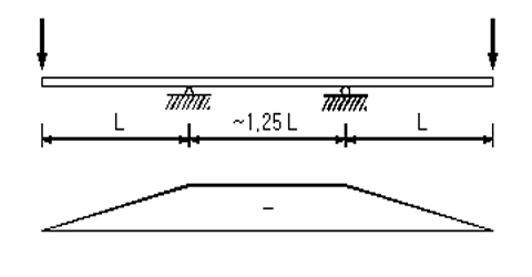
The example of design
2@65m 2 span continuous
bridge
The main position's
section
positive moment area |
negative moment area |
 |
 |
TU=1.0
cm , TL=2.0 cm |
TU=2.6
cm , TL=2.2 cm |
The variation of
flange
a reference
In the case flange width of section presented in the
example of design is 3m , extensible maximum span
length is possible to 75m.
|
¡¡
The
method of improving stiffness at the inner support
in the steel box girder. |
65m-75m-65m 3 span
continuous bridge
The main position's
section
positive moment area |
negative moment area |
 |
 |
TU=1.6
cm , TL=2.2 cm |
TU=3.2
cm , TL=2.4 cm |
The variation of
flange
a reference
In the case flange
width of section presented in the example of design
is 3m , extensible maximum span length is
possible to 75m.
|
¡¡
The
method of improving stiffness at the inner support
in the steel box girder. |
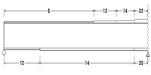
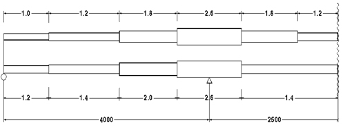
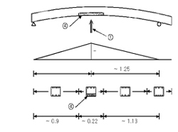
The process of construction
work in 3span continuous bridge
1?is lifting-up support,
2?is lifting-down support, 3?points slab concrete and
4?indicates concrete that is cast in lower part
of the steel box girder at the range
of negative
moment.
 |
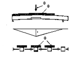 |
The state of lifting-up support after
connecting 2 spans first among 3 spans and then casting and curing concrete in
lower part of the steel box girder at the
negative moment range of the first
inner support. In this place projection
of right-hand is connected part of
the 3 spans.
¡¡
|
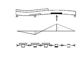
The
state of lifting-down inner support that
was lifted up after casting and curing concrete over full span except left-hand parts
of the third support in condition of lifting-up
the first inner support. |
 |
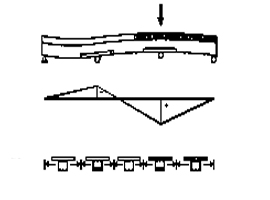 |
The state of lifting-up support to induce compression stress to concrete in
lower part of the steel box girder
after casting and curing concrete in lower
part of the steel box girder at the
negative moment range of the right-hand
support
¡¡
|
The
state of setting to support in condition
of lifting-up right-hand support after
casting and curing concrete in remaining spa |
|
¡¡
The
method of improving stiffness at the inner support
in the steel box girder. |
simple-multi span
steel box girder bridge for rahmen by Down-up.(patent
a public notice Number. 10-2000-058716)
This method in simple pan composite
girder construct is treated as fixed-moved support and
it has fall-rise moved support It have introduce
compressing stress on the floor slab concrete of negative
moment area and the lower flange of positive moment
in fixed support. The method of construct in multi-span
composite girder structure have fall-rise a pier
part support of both ends. It have the floor slab
con'c of inner support and the lower flange of
positive moment area introduce compressing stress. Because
moment in fixed support is distributed at a bridge pier,
share about external force of beam is reduced. So
girder height and span can expect reduction and extension
effect about 20%. Moreover, Parapet wall of one
side abutment in fixed support and floor slab con'c
places as one body therefore expansion joint and lower part can realize excellent effect and it has considerable
aseismicity. In the multi-span case, because support's
falling and rising work is accomplished in
a bridge pier, work's convenience and safety being superior
by far. And it can remove construction joint's
occurrence by simultaneous placing of floor
slab con'c.
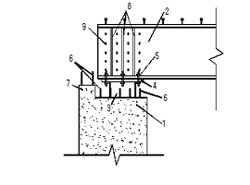
This method in
simple-span can happen big moment in fixed support. First
it has buried H-steel and after welding of connection
plate for steel box the lower part flange's connection
on the upside, it has connect completely by lower
part flange and bolt or welding. Here, at bridge seat
and parapet wall take out bar in advance. Including
the upper part floor slab, bridge seat, parapet wall
and steel box girder's web also lower part flange
is placed the same time. So it can do part of complete
fixed support. Steel box girder is reinforced by
install of stiffener. Not only the upper flange
steel girder but web install the stud, there it has greatly
improved the con'c composite effect. |
¡¡
The
method of improving stiffness at the inner support
in the steel box girder. |
2span continuous
steel box gird composition bridge
simple span steel box gird
composition bridge |
2span continuous steel box
gird composition bridge |
After
steel is installed simply, one end is fixed
and other end is downed state |
After
steel is installed extend 2 span, on the
base of inner support part,
state
that is downed both abutment part |
state
that placing floor slab con'c extend all
section |
state
that placing floor slab con'c extend all
section |
After
floor slab con'c is cured,
state
that compressed stress is introduced in
floor slab con'c that has risen
movement
support |
After
floor slab con'c is cured,
state
that compressed stress is introduced in
floor slab con'c that has risen
both
abutment part's support point |
|
¡¡
The
method of improving stiffness at the inner support
in the steel box girder. |
The process of construction
work in 3span continuous steel box gird composition
bridge
After
steel is installed extend 3 span, on the
base of the 2,3 inner support part,
state that is downed both abutment
part |
state
that placing floor slab con'c extend all
section |
After
floor slab con'c is cured, state that
compressed stress is introduced in floor
slab con'c that has risen both abutment
part's support point |
|
¡¡
|
|
|
|