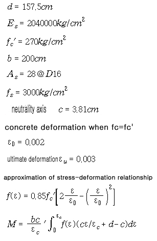
| |
|
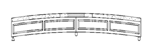
Improvement of bridge's
ability and repair&reinforcement method
Improvement of ability
method of simple and continuous span P.S.C
and
the Preflex composite bridge by Up-Down Method |
 Improvement
of ability and repair&reinforcement method of P.S.C
and the Preflex continuous beam
bridge Improvement
of ability and repair&reinforcement method of P.S.C
and the Preflex continuous beam
bridge
( patent 10-1999-007572,
patent 10-1999-045825, patent 10-1999-04582)
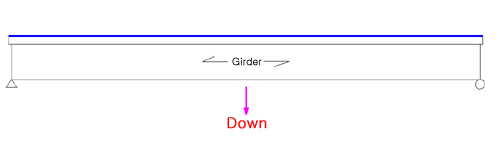
1. Introduction
1. brief
beam bridge of P.S.C & Preflex connecting
existing simple method is acted constructal moment redistribution.
At this time , because it occur negative moment in continuous
span , concrete of slab is cracked and problem of a
drop bridge' persistence is occured.
[this
method of construction is improvement of ability method
introducing the compressive force using Up-Down
Method at concrete of slab negative moment.
this method improve by DB-24 then existing P.S.C and
the Preflex.
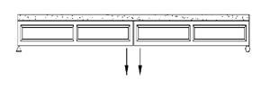
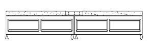
2. construction method
1) this method of construction part removing
slab
after removing slab at negative moment
of P.S.C and the Preflex., it arrange reinforce and
make concrete except the section inside support 0.1L.
this time, cross beam lower neutrality axis make concrete.
then the remander section is made concrete, cure the
concrete surface, after down, finish.
2) this method of construction entirety
removing slab
after
removing the entirety slab., it make concrete
at the section positive moment. then cure the concrete
surface, up support, it make concrete at the section
negative moment, it is finished making bridge by down
support.
|
Improvement of bridge's
ability and repair&reinforcement method
Improvement of ability
method of simple and continuous span P.S.C
and
the Preflex composite bridge by Up-Down Method |
repair&reinforcement
method
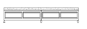
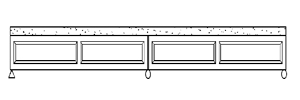
1. simple bridge
when it need to change slab of existing bridge,
equal upper step. only addition breaking concrete.
if existing bridge slab do not change, the step is the
next.
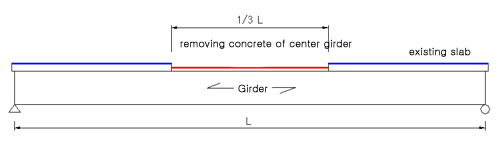
removing concrete of center
girder( preserving existing reinforced rod) |
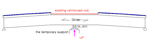
equipping the temporary
support & up girder |
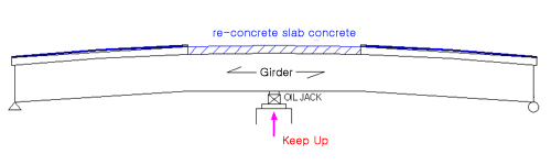
concrete
slab concrete at center and cure the
concrete surface. |
remove the temporary support and
falling girder ( introducing compressive
at the lower part girder) falling
|
|
¡¡ ¡¡
Improvement of bridge's
ability and repair&reinforcement method
Improvement of ability
method of simple and continuous span P.S.C
and
the Preflex composite bridge by Up-Down Method |
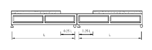
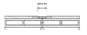
2. continuous
bridge
improvement ability
method's step of continuous 2 span P.S.C & Preflex
composite bridge by part removing slab method
production
step |
construction
step |
order chart |
STEP1 |
part removing
slab concrete & connecting |
 |
STEP2 |
concreting
partly slab concrete |
 |
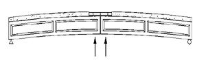
STEP3 |
up inner support |
 |
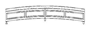
STEP4 |
entirety
removing slab concrete |
 |
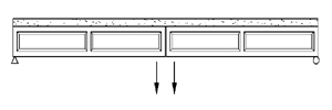
STEP5 |
down inner
support |
 |
STEP6 |
completion |
 |
|
Improvement of bridge's
ability and repair&reinforcement method
Improvement of ability
method of simple and continuous span P.S.C
and
the Preflex composite bridge by Up-Down Method |
improvement
ability method's step of continuous 2 span P.S.C &
Preflex composite bridge by entirety
removing slab method
production
step |
construction
step |
order chart |
STEP1 |
part removing
slab concrete & connecting |
 |
STEP2 |
concreting
partly slab concrete |
 |
STEP3 |
up inner support |
 |
STEP4 |
entirety
removing slab concrete |
 |
STEP5 |
down
inner support |
 |
STEP6 |
completion |
 |
|
Improvement of bridge's
ability and repair&reinforcement method
Improvement of ability
method of simple and continuous span P.S.C
and
the Preflex composite bridge by Up-Down Method |
effect improvement
ability of existing bridge
1. simple bridge
the subject
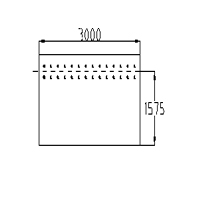
bridge : the location Imshhil-Gun ,Chollabuk-Do, simple
support PSC Beam
bridge, Sasun overhead bridge
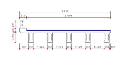
length
of girder 17.4m, length of bridge 18m, wide of bridge
9.25m
It has
been completed at 1973 , the second grade
effect : The basis durability increases
form DB-20 to DB-29
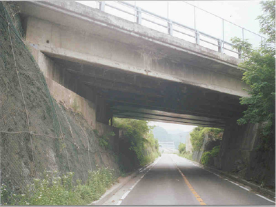
<a panoramic view>
<cross view>
|
Improvement of bridge's
ability and repair&reinforcement method
Improvement of ability
method of simple and continuous span P.S.C
and
the Preflex composite bridge by Up-Down Method |
Sasun overhead
bridge of The rising quantity, the falling quantity
and occurring stress at final
step
classification
¡¡ |
inner
span |
outside
span |
the rising force
¡¡ |
11.97 ton |
13.68
ton |
the falling force
¡¡ |
-17.79
ton |
-19.51
ton |
the rising displacement
¡¡ |
0.63
cm |
0.72
cm |
the falling displacement
¡¡ |
-0.42
cm |
-0.46
cm |
final stress
¡¡ |
the lower
beam
¡¡ |
-2.24
Kg/cm2
(compressive) |
10.69
Kg/cm2
(tension) |
the
upper slab
¡¡ |
-50.66
Kg/cm2
(compressive) |
-56.25
Kg/cm2
(compressive) |
classification
¡¡ |
before
improvement of ability |
after
improvement of ability(basic design) |
the
comparison |
Sasun
overhead
bridge
(L=18.0m) |
design load
¡¡ |
DB_18 |
DB-24 |
|
The basis durability
¡¡ |
DB-20 |
DB-29 |
45%
increase |
|
Improvement of bridge's
ability and repair&reinforcement method
Improvement of ability
method of simple and continuous span P.S.C
and
the Preflex composite bridge by Up-Down Method |
2. continuous
bridge ( basic design )
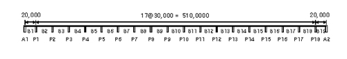
the subject bridge : the
location Ulsan city, simple support of 20m span , continuous
2 span of 20m span & continuous 3 span of 30m span,
PSC Beam bridge.
length
of girder 550m
the
second grade
effect
: The basis durability increases form DB-18 to DB-37
yaemdong direction
myoungchondong
direction
myoungchon large bridge's general
view
(a) center of span |
(b) end point
of span |
(a) center of span |
(b) end point
of span |
20m PSC Beam's general view 30mPSC
Beam's general view
¡¡ |
Improvement of bridge's
ability and repair&reinforcement method
Improvement of ability
method of simple and continuous span P.S.C
and
the Preflex composite bridge by Up-Down Method |
myoungchon
large bridge's of The rising quantity, the falling quantity
and occurring stress at
final step
classification |
PSC Beam span L=30m
¡¡ |
continuous
2 span
|
continuous
3 span |
the rising force |
24.59
ton |
14.28
ton |
the falling force |
-17.64
ton |
-8.26
ton |
the rising displacement |
6.22
cm |
3.61
cm |
the
falling displacement |
-3.86
cm |
1.81 cm |
final
stress |
the
section of positive moment |
the lower beam |
12.31 Kg/cm2
(tension) |
10.69 Kg/cm2
(tension) |
the
upper beam |
-86.57
Kg/cm2
(compressive) |
-88.50
Kg/cm2
(compressive) |
the
upper slab |
-14.79
Kg/cm2
(compressive) |
-16.33 Kg/cm2
(compressive) |
the
section of negative moment |
the
lower beam |
-131.4
Kg/cm2
(compressive) |
-114.71
Kg/cm2
(compressive) |
the
upper beam |
16.46
Kg/cm2
(tension) |
-5.42
Kg/cm2
(compressive) |
the
upper slab |
12.75 Kg/cm2
(tension) |
0.47
Kg/cm2
(tension) |
classification
¡¡ |
before improvement
of ability |
after improvement
of ability(basic design) |
the
comparison |
simple
support(L=20m) |
design load |
DB-18 |
DB-24 |
¡¡ |
The basis durability |
DB-18 |
DB-26 |
30%
increase |
continuous
2 span (L=20m) |
design load |
DB-18 |
DB-24 |
¡¡ |
The basis durability |
DB-20 |
DB-33 |
65%
increase |
continuous
3 span (L=30m) |
design load |
DB-18 |
DB-24 |
¡¡ |
The basis durability |
DB-20 |
DB-37 |
85%
increase |
|
Improvement of bridge's
ability and repair&reinforcement method
Improvement of ability
method of simple and continuous span P.S.C
and
the Preflex composite bridge by Up-Down Method |
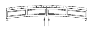
the method
connecting at the section inside support
it is point that
bending tension moment at upper girder and bending compression
moment at upper girder for continuing P.S.C and the
Preflex Beam.
1. method A (P.S.C Beam)
For bending tension stress at continuing
support using chemical anchor at PSC Beam's
upper, it correspond effectively, and connecting
with girder is planed for compressive
stress at lower girder.
Fig. a
Fig. a (the method connecting P.S.C
Beam)
2. method B (Preflex Beam)
bending tension stress at
connecting at the section support at upper girder and
compressive stress at lower girder is corresponded by
effectively connecting Beam
and Beam.
Fig. b (the method connecting Preflex
Beam)
|
Improvement of bridge's
ability and repair&reinforcement method
improvement
of ability method using crack-fasten of P.S.C Beam acting
bending crack |
improvement
of bridge's ability and repair&reinforcement method
*
<improvement of ability method using crack-fasten
of P.S.C Beam acting bending crack>
( patent number 10-1999-007572 , patent number
10-1999-045825 ,
patent number 10-1999-04582
)
1. outline
Presently existing bridge have many problem.
so it require repair & reinforcement
existing
method of repair & reinforcement have variety problem.
this method of construction overcome the
problem of other existing method of repair
& reinforcement : it is made improvement of unreliable
injecting by loading pre-load at structure
occurring bending crack and pure into injection. then
it is made improvement of repair & reinforcement
by getting rid of pre-load. the reason is
that bending crack concrete occur compressive stress.
so this method of repair & reinforcement
is fitting and trusting.
|
Improvement of bridge's
ability and repair&reinforcement method
improvement of ability
method using crack-fasten of P.S.C Beam acting bending
crack |
construction
step and stress view
¡¡ |
Improvement of bridge's
ability and repair&reinforcement method
Iimprovement of ability
method using crack-fasten of P.S.C Beam acting bending
crack |
¡¡
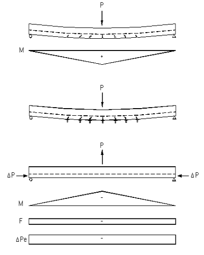
Fig. 2 force of construction by stages
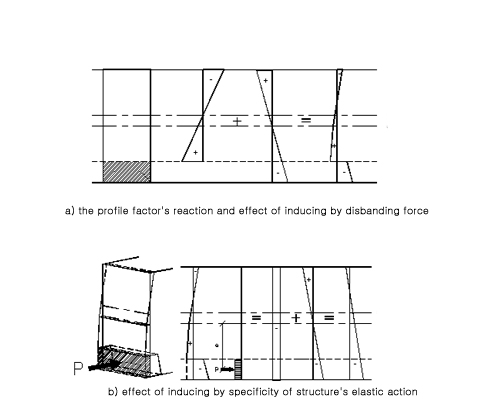
Fig. 3 effect of inducing stress
¡¡ |
Improvement of bridge's
ability and repair&reinforcement method
improvement of ability
method using crack-fasten of P.S.C Beam acting bending
crack |
experiment
view
(a)
loading pre-load (b)
injecting epoxy resins
and
curing the concrete surface
Fig. 4 loading pre-load and injecting
epoxy resins
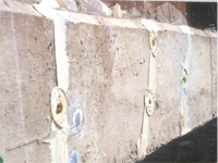 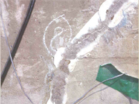
Fig. 5 being completed hardening of
injecting
table 1 loading-deflection relationship
load |
deflection
before repair&reinforcement |
deflection
after repair&reinforcement |
measuring
date of experiment |
analysis
of finite element |
measuring
date of experiment |
analysis
of finite element |
3 |
5.78 |
6.89 |
5.06 |
5.62 |
6 |
14.16 |
13.79 |
9.26 |
11.24 |
9 |
20.47 |
20.68 |
13.88 |
16.87 |
12 |
25.73 |
27.58 |
23.94 |
22.48 |
16 |
36.4 |
36.77 |
26.6 |
29.97 |
20 |
45.50 |
45.96 |
37.5 |
34.46 |
24 |
- |
- |
45.27 |
44.95 |
28 |
- |
- |
52.43 |
52.44 |
32 |
- |
- |
60.50 |
59.94 |
34 |
- |
- |
65.95 |
63.68 |
37 |
- |
- |
72.00 |
69.3 |
this date is showed : comparing measuring
date of experiment with analysis of finite
element
|
Improvement of bridge's
ability and repair&reinforcement method
improvement of ability
method using crack-fasten of P.S.C Beam acting bending
crack |
comparing a method of
construction
we apply this method to simple
PSC composition beam of reinforcing as External
Prestressing method. then we compare stress condition
* the subject bridge
: moonle overpass
* the time
of completed : 1979
* type of
upper structure :single span PSC composit beam
*
external state : deterioration of slab and girder, crack
occur at PSC beam, bending
crack length 20~80cm, wide 0.1~0.3m. result of
crack's deep, crack exceed
reinforce rod's cover.
so
need structural reinforcement.
*
profile factor's rate : 15%
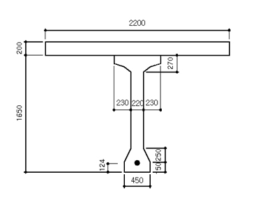
Fig. 6 moonle overpass's cross section
|
Improvement of bridge's
ability and repair&reinforcement method
improvement of ability
method using crack-fasten of P.S.C Beam acting bending
crack |
|
table 2 comparing stress in service load
classification
¡¡ |
upper section
Kgf/cm2 |
low section
Kgf/cm2 |
the
comparison |
stress
before
damage |
DB-18 |
-91.23 |
12.07 |
exceeding
allowance stress |
DB-24 |
-97.88 |
32.92 |
stress after damage |
DB-18 |
-96.29 |
39.89 |
DB-24 |
-102.94 |
60.79 |
External
Prestressing |
DB-18 |
-77.29 |
-12.60 |
satisfactory
design load |
DB-24 |
-83.93 |
8.3 |
Preloading |
DB-18 |
-91.16 |
-4.20 |
DB-24 |
-97.81 |
16.70 |
resulting of comparing this method to External
Prestressing method by inducing at simple PSC
beam, the lower part of PSC beam inducing stress
quality is smaller 8.4kgf/cm2 then External Prestressing
method, but this method secure durability except
additional repair&reinforcement method.
|
Improvement of bridge's
ability and repair&reinforcement method
Repair method at inner
support of continuity Steel Box Girder using injection
concrete |
Repair method
at inner support of continuity Steel Box Girder using
injection concrete
1. outline
This method is repair method
: after clearing rot, lowering stiffness is repair.
* rotting of inner support in Box wall
water store at inner support
because of camber. so it occur rotting of inner
support in Box wall
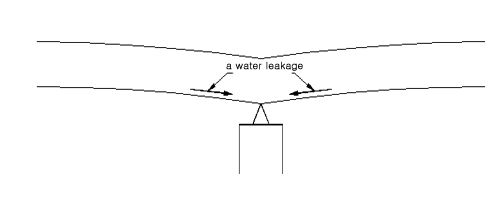
Fig. 1 flow of water leakage
by camber
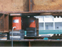
* Repair method using injection concrete
if rotting of inner support in
Box wall is removed like Fig. 2 , thickness of flange&web
is drop and stiffness is reduction.
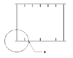 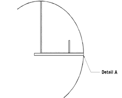
Fig. 2 Box inner wall occurring
rot
|
Improvement of bridge's
ability and repair&reinforcement method
Repair method at inner
support of continuity Steel Box Girder using injection
concrete |
¡¡
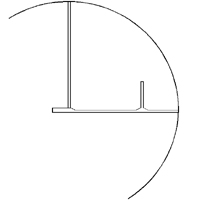
Fig. 3 after removing
corrosion
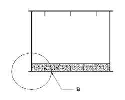 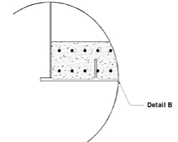
Fig.4 Being reinforced at section
negative moment by injecting concrete.
|
Improvement of bridge's
ability and repair&reinforcement method
improvement of continuity
bridge's ability method using weight |
|
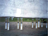
1. outline
Presently existing continuity bridge
was constructed without preparing negative moment
at inner support. so slab concrete was cracked and stiffness
and durability was decline. finally, this
crack is made dark action as structure and dark
effect as using & durability.
improvement
of continuity bridge's ability method using weight is
a method introducing compressive stress
at negative moment inner support. so crack is prevented
and this method have an advantage at deflection &
shock.
|
Improvement of bridge's
ability and repair&reinforcement method
improvement of continuity
bridge's ability method using weight |
2. improvement of continuity
bridge's ability method using weight
step 1 removing slab
at section negative moment
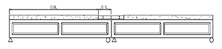
step 2 loading
after repairing across beam
load is decided by tension
reinforced rod quantity and moment . this moment is
that across beam's ability resistant.
step
3 removing after concreting slab at section negative
moment
through step 1~step 3 , induce compressive
stress at section negative moment's slab.
so it is
resisted negative moment
acting live load. this method is applied at plate continuous
bridge and steel box continuous bridge's repair method
and over 3 span.
|
Improvement of bridge's
ability and repair&reinforcement method
improvement of continuity
bridge's ability method using weight |
3. structure
computation's example
structure computation perform for
ability application this method , actually constructed
2 span continuous preflex bridge, using
finite element analysis modeling.
this modeling is 2 span continuous
bridge , span length 45m, this bridge is location
Inchon city,
public overpass.
Fig. 1 is cross section view of preflex bridge. Fig.
2 is cross section view of 1 preflex
beam. Fig. 3 is cross section view of across beam of
section positive moment and section
negative moment. and table 1, table 2 is section's
character using finite element analysis.
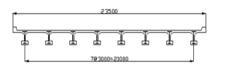
Fig. 1 cross
section view of preflex bridge
table 1 section's character of preflex beam
beam
¡¡ |
beam+slab |
beam |
A |
2524 |
1522 |
Ix |
8678835.2 |
4581683.8 |
Iy |
4634171 |
570109.1 |
J |
1885243.8 |
277118.8 |
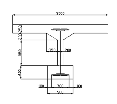
Fig. 2 cross section view of preflex
beam
|
Improvement of bridge's
ability and repair&reinforcement method
improvement of continuity
bridge's ability method using weight |
|
table 2 section's character of across
beam and slab
¡¡ |
across
beam |
slab |
across
beam+slab |
across
beam of connecting section |
across
beam of connecting section-slab |
A |
370.6 |
323.5 |
694.1 |
2491.6 |
2168.1 |
Ix |
340477.9 |
16850 |
1087095.2 |
6110930.9 |
3897394.0 |
Ix |
27794.1 |
326225.5 |
354019.6 |
2927906.1 |
2601680.7 |
J |
111176.5 |
67402.0 |
178578.5 |
5880763.4 |
5813361.0 |
¡¡
Fig. 3 across beam and slab
(1) detail construction step
¨ç adhering strut
a-1.
cross section of beam
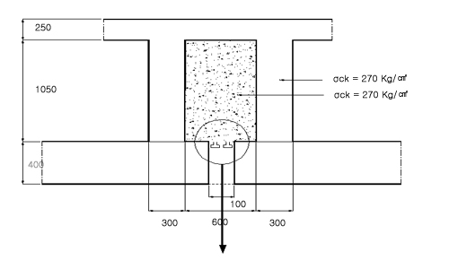
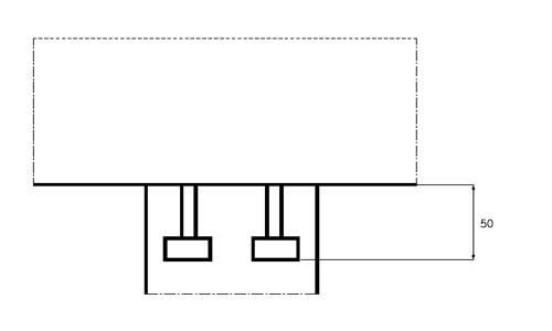
Fig. 4 crossing section with
beam , adhering strut at lower across beam
|
Improvement of bridge's
ability and repair&reinforcement method
improvement of continuity
bridge's ability method using weight |
|
a-2. cross section view of connecting
section
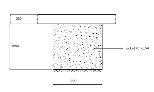
Fig. 5 adhering strut at lower
across beam
b-1. a ground plan ( view at down
)
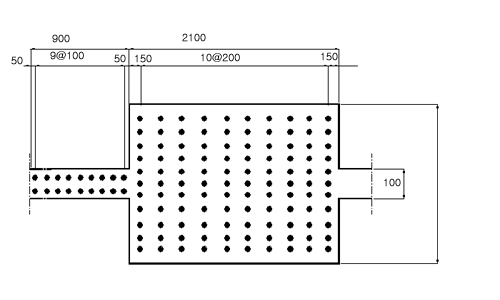
Fig. 6 adhering strut's shape at down
¨è injecting concrete
a-1. cross section of beam
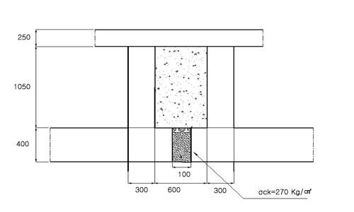
Fig. 7 injecting crossing section
with beam
|
Improvement of bridge's
ability and repair&reinforcement method
improvement of continuity
bridge's ability method using weight |
|
a-2. cross section view of connecting
section
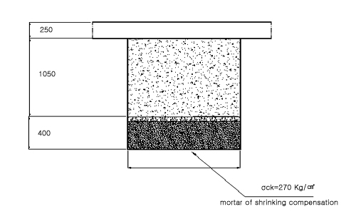
Fig. 8 injecting concrete of
connecting section
¨é removing slab
a-1. cross section
of beam

Fig. 9 removing upper flange at crossing
section with beam
|
Improvement of bridge's
ability and repair&reinforcement method
improvement of continuity
bridge's ability method using weight |
|
a-2. cross section view of connecting
section
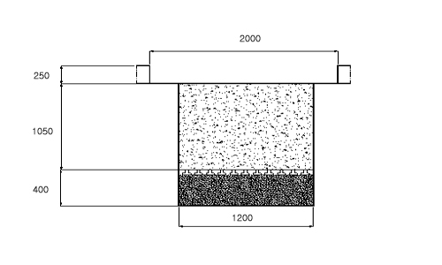
Fig. 10 removing upper flange at connecting
section
¨ê injecting epoxy at section across
beam crack
a-1.
cross section of beam
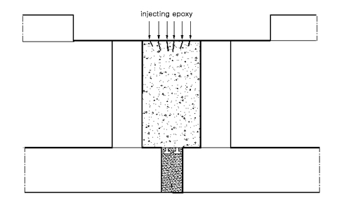
Fig. 11 injecting epoxy at across
beam upper cracking section of crossing section
a-2. cross section view of
connecting section
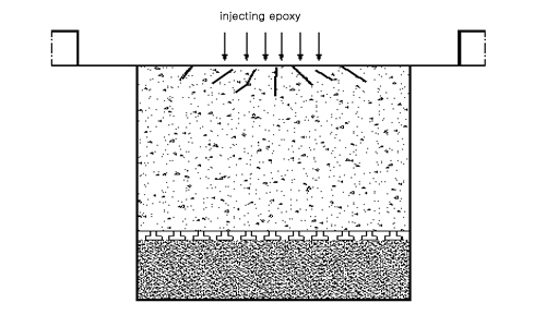
Fig. 12 injecting epoxy at across
beam upper cracking section of connecting section
|
Improvement of bridge's
ability and repair&reinforcement method
improvement of continuity
bridge's ability method using weight |
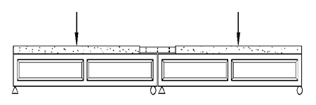
¨ë loading
a) bending moment of ability
removing slab's across beam
* the out
side of across beam
M=204.5
tm
* inner across beam
 |
Improvement of bridge's
ability and repair&reinforcement method
Iimprovement of continuity
bridge's ability method using weight |
|
b) loading weight
result finite element analysis, negative moment 330ton
occur when 100ton load at G beam. so weight is 63.3ton
for occurring negative moment 204.5ton. so weight is
60ton.
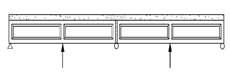
c) loading weight
*step 1
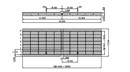
Fig. 13 cross section and a
ground plan of loading step 1's weight
*step 3
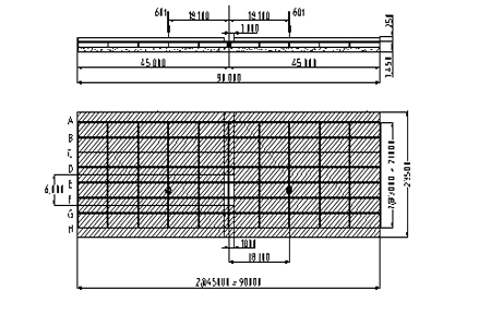
Fig. 14 cross section and a
ground plan of loading step 3's weight
|
Improvement of bridge's
ability and repair&reinforcement method
improvement of continuity
bridge's ability method using weight |
¨ì concreting slab and release
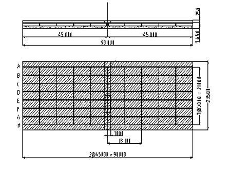
Fig. 15 cross section and a ground
plan of concreting slab and release
(2) final stress
table 4 final stress of weigh and
live load
¡¡ |
the out side
of across beam |
the inner
side of across beam |
the point
of load |
bending
moment by live load
¡¡ |
412.8tm |
412.8 tm |
¡¡ |
upper
stress by live load
¡¡ |
28.57 Kg/cm2
(tension) |
42.85 Kg/cm2
(tension) |
¡¡ |
bending
moment by weigh
¡¡ |
235.32 tm |
248.82 tm |
147 tm |
upper
stress by weigh
¡¡ |
17.53 Kg/cm2
(compession) |
25.8 Kg/cm2
(compression) |
21.9 Kg/cm2
(tension)the (section lower casing) |
final
upper stress
¡¡ |
11.04 Kg/cm2
(tension) |
17.05 Kg/cm2
(tension) |
¡¡ |
|
Improvement of bridge's
ability and repair&reinforcement method
repair&reinforcement
method of pier's coping |
1. outline
this method repair and reinforce crack
acting at pier's coping supporting the upper
part bridge.
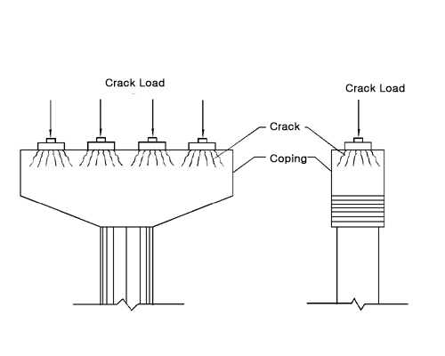
Fig. 1 cracking
shape
2. existing method of construction.
|
Improvement of bridge's
ability and repair&reinforcement method
repair&reinforcement
method of pier's coping |
Fig. 2 is existing method of construction. the method
have problem of maintaining
existing method using frequently have many problem.
|
Improvement of bridge's
ability and repair&reinforcement method
repair&reinforcement
method of pier's coping |
3. construction method
this method is that: after it load
cracking load at coping of acting crack, extend crack.
then using epoxy resins, fill crack, remove load. finishing.
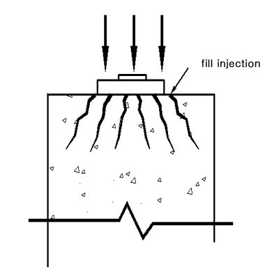
Fig. 3 after cracking load, fill injection
filling injection
3. effect
this method improve 150~200% of practical
coping durability as introducing compressive at total
coping.
|
|
|
|
|