|
¡¡
 Background of knowledge Background of knowledge
¡¡
This method is similar to a developed
steel box rahmen overhead bridge. The steel box beam is placed in
a simple beam system on the columns, and connected both ends of
simple beam by PSC steel bars. Oil jacks are placed between
the center of the beam and the PSC steel bars. After being
manufactured by this method, The beam is loaded by oil jacks. This
beam is continuous columns and PSC bars are eliminated. Results
of this method rise to positive moments to parts of negative moments
and negative moments to parts of positive moments. These moments
resist moments which are occurred by dead and live load. A
newly developed method, the prestressed steel box rahmen overhead
bridge using vertical load, decreases above 50% to sections of columns
and foundations when loaded a lower load, but disadvantages to parts
of positive moments and has difficulty in working for loading a
vertical load.
However the steel box whose parts
of center and ends are able to make variable sections which have
straight or curved, the former method is slenderer than the latter
for appearance of the beam and decreases about 30% than a simple
beam system for quantity of steel.
¡¡
The method of construction
¡¡
Manufacture and construction of the prestressed
steel box rahmen overhead bridge using PSC steel bar
The construction program for this
method is described as follows
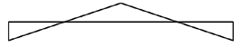
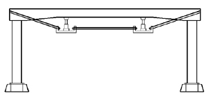
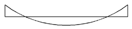
STEP1 : The steel box beam is placed in
a simple beam system on the column
This method is similar to
a developed steel box rahmen overhead bridge. The
steel box beam is placed in a simple beam system on
the column. |
(Fig. 1) |
¡¡
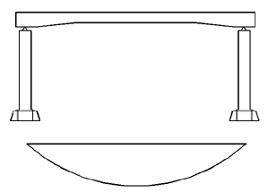
STEP 2 : After being installed PSC bars
and oil jacks to both ends of the beam, the beam is prestressed.
When loaded with oil jacks,
tendon force occurred in PSC bars. This force rise
to negative moments to parts of positive moments and
positive moments to parts of negative moments for the
steel box beam. The number of oil jacks is 1 when the
length of beam is about 50m, and 2 when the length
of beam is longer than 50m. |
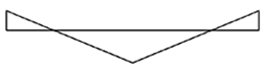
(Fig. 2)
¡¡
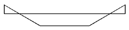
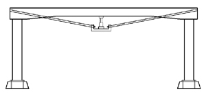
(Fig. 3) |
¡¡
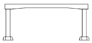
STEP 3 : The steel box beam is continuous
columns and tendon forces is eliminated
¡¡
STEP 4 : The overhead bridge is completed
When the overhead bridge is
completed, the figure 5 is the moment diagram by dead
and live load. However negative moments rise to both
ends of the beam and positive moments rise to center
of the beam, these moments is equal to moments of (4). |
(Fig. 5) |
|